Science Chapter 4 - Effects Of Electric Current
SSC, SCIENCE PART I, NEW SYLLABUS, FOR BOARD EXAM 2020,
Question 1:
Tell the odd one out. Give proper explanation.
a. Fuse wire, bad conductor, rubber gloves, generator.
b. Voltmeter, Ammeter, galvanometer, thermometer.
c. Loud speaker, microphone, electric motor, magnet.
ANSWER:
a. The odd one out is generator. It is an electrical device for producing electricity. Fuse wire, bad conductor and rubber gloves have high resistance and are used for blocking electricity. Thus, they can be used as a safety measure against heavy electricity.
b. The odd one out is thermometer. It is an instrument for measuring the temperature of a body. Rest of the three are electrical instruments based on the phenomenon of electromagnetism and are used for measuring some electrical parameters such as current and voltage.
c. The odd one out is magnet. Loud speaker, microphone and electric motor are based on the phenomenon of electromagnetism.
Question 2:
Explain the construction and working of the following. Draw a neat diagram and label it.
a. Electric motor
b. Electric Generator (AC)
ANSWER:
a. Motor principle: The basic principles on which the electric motor works is the magnetic effect of current. A current carrying rectangular coil starts rotating when placed in a magnetic field.
Construction:

 The given figure illustrates the internal parts of a simple electric motor. A motor consists of a rectangular coil MNST of insulated copper wire. The coil is placed between two magnetic poles such that the magnetic field acts normal on lengths MN and ST. The coil is connected with two carbon brushes at points A and B respectively. The inner sides of these carbon brushes are in contact with half rings C and D, which are insulated and in contact with an axle (not shown in the figure).
Working: When a current is allowed to flow through the coil MNST by closing the switch, the coil starts rotating anti-clockwise. This happens because a downward force acts on length MN and at the same time, an upward force acts on length ST. As a result, the coil rotates anti-clockwise.
 The current in length MN flows from M to N, and magnetic field acts from left to right normal to length MN. Hence, according to Fleming’s left hand rule, a downward force acts on length MN. Similarly, the current in length ST flows from S to T, and magnetic field acts from left to right normal to its length. Hence, an upward force acts on length ST. These two forces cause the coil MNST and the axle to rotate anti-clockwise.
After half-rotation, the position of length MN and ST get interchanged. Simultaneously, half ring D comes in contact with brush A and half ring C comes in contact with brush B respectively. Hence, the direction of current in coil MNST gets reversed and flows through TSNM.
An electric device that reverses the direction of current in a circuit is called a commutator. Thus, the split ring acts as a commutator of the electric motor. Now, due to the reverse direction of current in lengths MN and ST, an upward force acts on length MN, which pushes it up and a downward force acts on length ST, which pushes it down. As a result, the coil MNST further rotates anti-clockwise. The reversal of the current through the coil MNST repeats at each half-rotation, while its anti-clockwise rotation continues.
b. Electric Generator principle : An electric generator is a machine that generates electricity by rotating its rotor in a magnetic field. Thus, it converts mechanical energy into electrical energy.
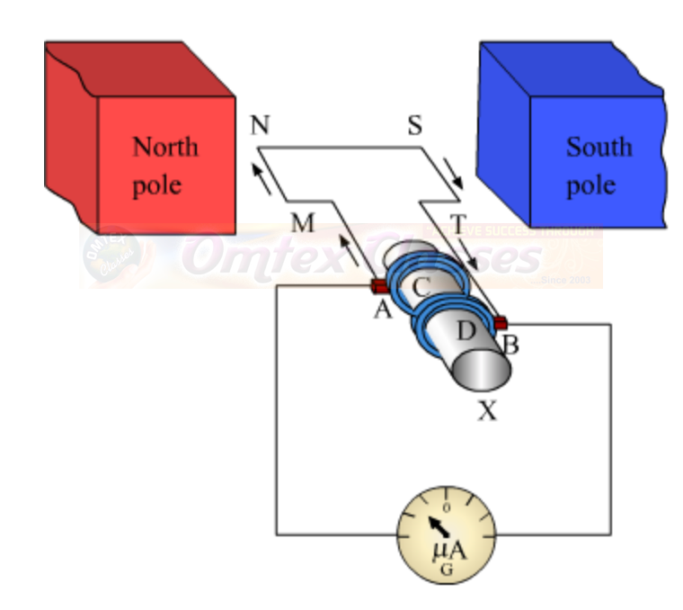
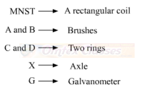
Construction: A generator consists of a rectangular coil MNST of insulated copper wire placed between two strong magnetic poles. The two ends of the coil MNST are connected with brushes A and B of rings C and D respectively. The inner sides of the rings are insulated. They are attached with an axle X, which can be rotated mechanically. Brushes A and B are connected with a galvanometer that can measure the flow of current in coil MNST.

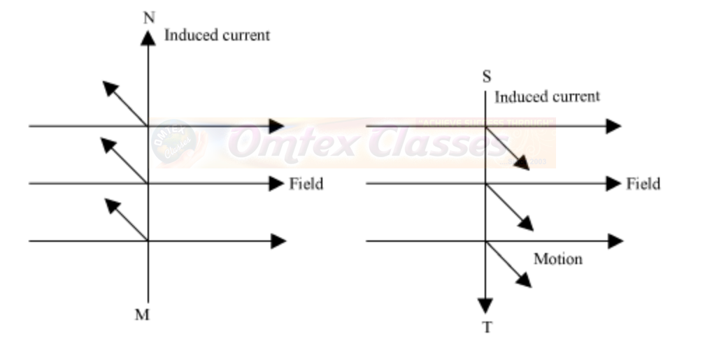
 Working: When the axle is rotated, lengths MN and ST move up and down respectively. Since lengths MN and ST are moving in a magnetic field, a current is induced in these lengths caused by electromagnetic induction. The direction of the induced current in both the lengths is given by Fleming’s right hand rule.
 Since length MN is moving upwards in the magnetic field that acts from left to right, the direction of the induced current will be from M to N. Similarly, the direction of the induced current in length ST will be from S to T. Hence, an induced current will set up in the coil in the direction MNST, which produces deflection in the galvanometer.
After half-rotation, length MN starts moving down, whereas length ST starts moving up. The direction of the induced current in the coil gets reversed i.e., the induced current will now flow from T to M via S and N i.e., TSNM. Therefore, we can conclude that after each half-rotation, the direction of the induced current is reversed. This current is called an alternating current (AC). An AC reverses its direction after equal time intervals.
Question 3:
Electromagnetic induction means-
a. Charging of an electric conductor.
b. Production of magnetic field due to a current flowing through a coil.
c. Generation of a current in a coil due to relative motion between the coil and the magnet.
d. Motion of the coil around the axle in an electric motor.
ANSWER:
Electromagnetic induction means generation of a current in a coil due to relative motion between the coil and the magnet.
Question 4:
Explain the difference:
AC generator and DC generator.
ANSWER:
Sl. No.
Differentiating Property
AC Generator
DC Generator
1
Definition
AC generator is a mechanical device which converts mechanical energy into AC electrical power.
DC generator is a mechanical device which converts mechanical energy into DC electrical power.
2
Direction of Current
In an AC generator, the electrical current reverses direction periodically.
In a DC generator, the electrical current flows only in one direction.
3
Basic Design
In an AC generator, the coil through which the current flows is fixed while the magnet moves. The construction is simple and costs are less.
In a DC generator, the coil through which the current flows rotates in a fixed field. The overall design is very simple but construction is complex due commutators and slip rings.
4
Commutators
AC generator does not have commutators.
DC generators have commutators to make the current flow in one direction only.
5
Rings
AC generators have slip-rings.
DC generators have split-ring commutators.
Sl. No.
|
Differentiating Property
|
AC Generator
|
DC Generator
|
1
|
Definition
|
AC generator is a mechanical device which converts mechanical energy into AC electrical power.
|
DC generator is a mechanical device which converts mechanical energy into DC electrical power.
|
2
|
Direction of Current
|
In an AC generator, the electrical current reverses direction periodically.
|
In a DC generator, the electrical current flows only in one direction.
|
3
|
Basic Design
|
In an AC generator, the coil through which the current flows is fixed while the magnet moves. The construction is simple and costs are less.
|
In a DC generator, the coil through which the current flows rotates in a fixed field. The overall design is very simple but construction is complex due commutators and slip rings.
|
4
|
Commutators
|
AC generator does not have commutators.
|
DC generators have commutators to make the current flow in one direction only.
|
5
|
Rings
|
AC generators have slip-rings.
|
DC generators have split-ring commutators.
|